This proposed application is intended to provide a safe and interactive venue through which facility management in dangerous environments can be performed in real-time. Though it is more applicable and geared towards industrial sites and environments with complex building systems, it could be suitable for medium to large commercial and residential buildings. This augmented reality (AR) interface will use something like the Microsoft HoloLens, Meta 2, or Leap Motion head-mounted display (HMD), and the user interaction is to be driven primarily by hand movements recognized and interpreted by the HMD’s built-in cameras. Along with the clear display screen which allows for the user to see through the interface to the surrounding real environment, dedicated output panels in the interface display building system status, room information, and other relevant information, as well as opportunities for user manipulation of the building systems.
At the onset of its use, the interface with panels closed provides optimal visibility for user while still having quick access to menu items. The following layout depicts an overview of the interface with panel organization:
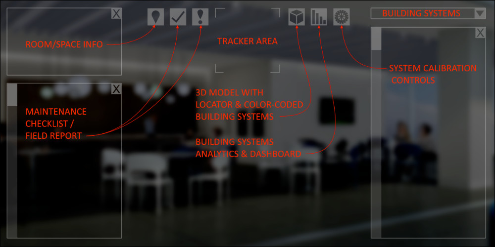
In a typical workflow, the user approaches a room in the building and locates the physical tracker image, in the form of QR codes or nameplates, for that particular room. The interface consists of a dedicated area for overlaying a tracker image that the HMD will recognize and attribute to the room’s corresponding information. It also uses the tracker to geo-locate a visualization of building systems and controls in the interface superimposed over the real environment. The interface then displays this room’s specific information, including any maintenance checklists and building systems pertaining to that room. Room-specific information allows the user to focus on its features and not overwhelmed with too much information all at once. Since the tracker is recognized only when the user enters a room, then the space on the interface for the tracker can also be used as an output window for other information or for viewing through to the real environment.
Spatial coordination for the user’s own information and the documentation that may be necessary for facilities management protocol is clarified through the display of a key plan in the form of a 3D model in the interface. The locator in the key plan helps coordinate the user to his/her location relative to the building and any building systems, which can be displayed in the 3D model. While the room information is specific to a room, this 3D model visualization grants the user access to the entire facility’s infrastructure.
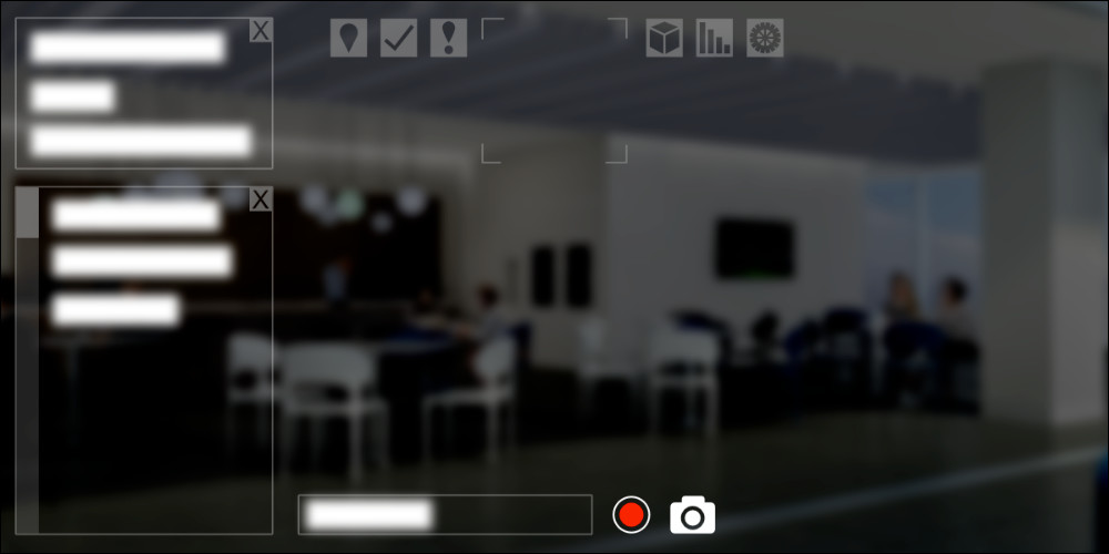
As a regular facility management task, the interface is aimed to expedite and streamline the documentation of observations, issues, and relay of information to an archive, as well as to dynamically respond to maintenance on-site. Anomalies and maintenance performance checklists are displayed in the field report area of the interface based on the requirements of the room and the selected building system. Scroll bars expand depending on the number of line items included. Photographs can be documented through the HMD’s cameras and a microphone serves as another form of input for recording field report observations as individual line items in this section.
The system calibration section provides access to building systems applicable to the room in which the user is located. Examples of building systems include electrical, mechanical, plumbing, etc. For each building system available in the drop-down menu, different types of controls and analytics will become available in the interface. The intent of these controls and graphics is to make modifications to the building systems remotely and without having to interface with hazardous equipment on a regular basis.
Analysis of Digital Medium Characteristics
The procedural characteristic of this digital medium is through the programmed software that organizes building information modeling (BIM) data for user access and manipulation, as well as ties to the site’s communication network. Input by the participant consists of the hand and finger movements and tracker images recognized by the HMD’s camera, resulting in real-time information displayed on the interface. The participatory characteristic is further supported by the user’s calibration of building systems and field report documentation through the interface. The records of documentation and system manipulations by the user are stored, relayed, and recalled through the communication network to build onto the encyclopedic characteristic. Spatial reference is provided through the tracker recognition that coordinates the user’s physical location relative to the site in a 3D model. Furthermore, the augmented reality interface displays a coordinated digital environment superimposed over the real environment.
Application Interface
This sketch is an initial pass at coordinating utilities in interface within a limited space and maintaining visibility through screen.
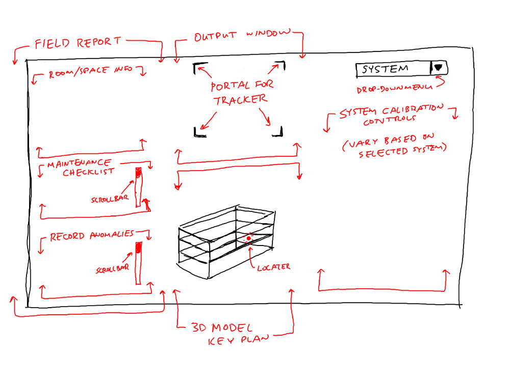
Upon detection of tracker (QR code), room information, checklist, available building systems, and 3D locator become available for use. Checklist items are toggled when complete and building systems are selected from drop-down menu.

Field report mode allows for inputting issue name, voice recording, and documenting through photographs with the camera.
Calibrating building systems is through the various controls available based on the selected building system. Live analytics in the form of different graphs and charts assist user in evaluating building system status.
